


 Digital Audio Cable--
What It Does and Why
Digital Audio Cable--As with a lot of home electronics goods, there's a considerable amount of nonsense surrounding digital audio cables. Getting this right is pretty easy, with straightforward product choices, but if you'd like to understand more about the whys and wherefores of digital audio cable, read on.
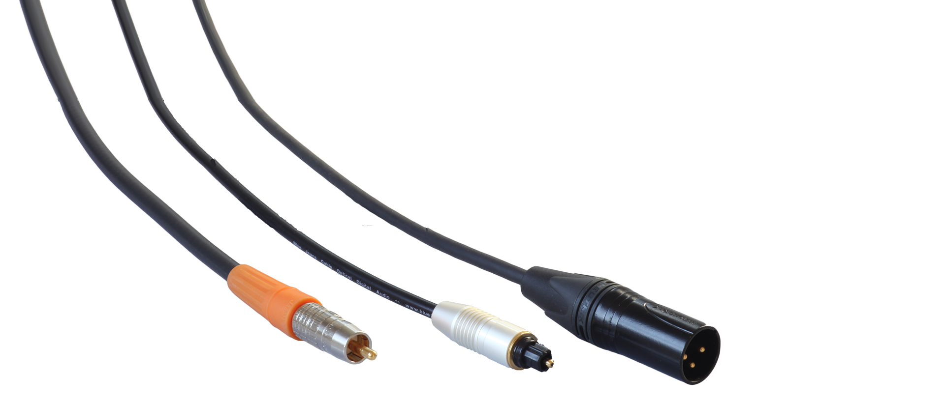
Three Standards, or One?We normally see digital audio in consumer devices as S/PDIF (sometimes labeled "coaxial digital audio"), or TOSLink (sometimes labeled "optical digital audio"), and in professional devices as AES/EBU. The three have, despite their very different connectors, cables and names, more in common than one might expect. All of them are basically the same system, with the same encoding structure. AES/EBU has some capabilities beyond the others and slight differences in protocol, with S/PDIF and TOSlink being sort of a subset of the AES/EBU universe. A TOSlink signal, if simply converted from flashes of light to voltage pulses, would feed a S/PDIF circuit just fine, and a S/PDIF signal fed into an AES/EBU input (an impedance transformer being a good idea here) will usually likewise work just fine.
The big difference between the three is the one we can see from the outside by looking at cable and connectors: TOSLink is optical, so can't talk to the others without some optical/electrical conversion. S/PDIF is run unbalanced in 75 ohm impedance coaxial cable, while AES/EBU is run balanced in 110 ohm twisted-pair cable.
Upside-Down Encoding:The encoding structure for digital audio is called "BiPhase Mark Code" or "Differential Manchester Encoding," and it's a tad different from what you might imagine. When data streams are encoded in binary, we think of the data as "ones and zeros," and we usually imagine those travelling through the cable as two discrete voltage levels, one representing one and the other representing zero.
But this structure is rather different. There are still two voltage levels, but every bit in the stream begins with a transition from one to the other. The difference between a one and a zero is that in a "one," there is another transition in the middle of the bit, while in the "zero" there is not. One peculiar aspect of this style of encoding is that one can invert the signal, and the data read from it will be the same. This encoding has implications for required bandwidth of the cable and for "cable-induced jitter," as we'll see.

Above is what a S/PDIF signal consisting of all zeros looks like. As you can see, each bit is marked with a transition, despite the fact that the value represented isn't changing at all from one bit to the next. In a more conventional binary encoding system, the above would be alternating ones and zeros. Also, as you can see, while we like to speak of this as a "square wave," it's not; the transitions are abrupt, but not instantaneous.

Above is a trace from the same disc player which generated the all-zeros trace, but this time with a mix of ones and zeros. As you can see, when there's a "one," the interval represented by a bit is split by a transition. Reading from the first complete bit on the left (the first "down") we see: 0001101100000
One-Way:All of these are one-way protocols: there can be some error detection at the receiving end, but there's no opportunity for error correction (unlike, for example, Ethernet, where a receiving device can signal back a request to resend a packet). The only answer to data errors is to do what you can to avoid them.
Bandwidth:Two channels of SPDIF running at a 192kHz sample rate, at 24 bits depth, gives us the highest data rate of SPDIF: about 9.2 Megabits per second. AES/EBU can run somewhat higher. What does that mean for S/PDIF cable bandwidth requirements?
Digital signals correspond to frequency in ways that are a bit strange to someone with an old-school RF way of thinking. In a conventional ones/zeros encoding arrangements with the two voltage levels representing one and zero, we normally think of the "frequency" of the signal as one half of the bitrate (since a sine wave contains one "up" and one "down" per iteration). That would give us 4.6 MHz for S/PDIF, but for that Differential Manchester Encoding. Since we now have the potential for double the rate of transitions, it really takes us back up to 9.2 MHz. But when we speak of frequency here, we're not really talking about frequency in quite the radio-signal sense. This isn't a carrier wave with the signal modulated onto it, where a transmission line just needs to behave well at the particular frequency of interest. A data stream will have a variable spectral density across a wide range of frequencies, and so what we want to see is some breadth of bandwidth: the ability to convey a large range of those frequencies faithfully.
And data signals, with sharp transitions between voltages, are not sine waves -- they are near-square waves (because an actual square wave, no matter how hard one tries, is really quite impossible). A square wave is an interesting mathematical critter: its equivalent can be calculated, in what's known as a Fourier transform, by summing an infinite series of the odd harmonics -- that is, multiples -- of the fundamental frequency. So, at 9.2 MHz we have the fundamental covered, but a great deal of the "squareness" of our near-square wave is in the third harmonic, taking us as high as 27.6 MHz. A bit more is at the fifth harmonic, taking us up as high as 46 MHz. And while the Fourier transform might look like just an abstract exercise in mathematics, the weird fact is that this is just how the real world behaves -- the spectral density of the signal extends not only below but also above the notional "fundamental" frequency.
So, 50 MHz or so of cable bandwidth is a good thing. And the good news? That's very easily achieved. Even the crummiest CATV coaxes are usually tested for reasonable performance up to 1 GHz, twenty times higher than we need. The precision SDI coaxes we use go well beyond that. Bandwidth, it's fair to say, will not be a problem, and the wavelengths here are long enough that the minor impedance mismatch that occurs in the cable-to-connector transition and the plug-to-jack interface will cause us no trouble.
Jitter:"Jitter" is the phenomenon which occurs when the sending and receiving clocks have trouble staying synchronized, and there's a lot written about jitter in the home audio context. Since the sending device is not listening to the receiving device, the clock speed cannot be set by any sort of two-way protocol; the sending circuit sends, and the receiving circuit has the job of synchronizing to it. Jitter can be a genuine problem, but that's mostly about the sending and receiving devices and not so much about us, so we'll limit ourselves to what we know well.
As with many things in life, timing isn't always perfect. The traces we've shown you above show pretty consistent, sharply defined bits, and one nice thing about these streams is that the bit length -- measured left to right -- is consistent. A steady clock in the source device makes it easier for the receiving device to ascertain and stick to the correct timing. But have a look at this trace, from a different player: it shows the kind of inconsistency of timing which can contribute to jitter, with some bits significantly longer than others.
 What About Cable-Induced Jitter?
You may see people fretting online from time to time about the phenomenon known as "cable-induced jitter." Cable-induced jitter is a real thing, but our advice is to not give it a moment's thought -- at least, not after you've read why.
Cable is never quite neutral. It never emits, at the far end, exactly what went in at the near end. The principal villains are things like return loss, which have the effect of taking those nice sharp voltage transitions and smooshing them out over time. The signal, as it travels through the cable, becomes somewhat "rounder" and the shoulders of those transitions less abrupt. Here's where that gets to be a potential jitter problem. If in a conventional encoding system we send a long string of alternating ones and zeros, we'll see a pretty regular wave at the receiving end -- rounded off a bit but still quite regular, and with its transitions still occurring at the same times relative to one another as in the source signal. But one thing you'll see, at least in high-speed signalling (not so evident on the traces shown on this page) notice is that the "one" frequently doesn't quite finish its upward trip before the leading edge of the next, downward transition starts to arrive. But if we run, say, four "ones" in a row, as inevitably will happen again and again, we'll see that voltage climb higher. The "rise" is being given more time to get its job done. Now, along comes the next bit: a zero. As the zero comes down the line, it brings the voltage down. But because the voltage has reached a higher peak after four consecutive "ones," it has farther to go. It will cross the mid-line late, compared to the performance when we were just alternating ones and zeros all the time. These inconsistent timings can cause what is known as "cable-induced jitter" -- the jitter is being worsened by the effects of losses in the cable.
But Differential Manchester Encoding doesn't really allow enough room for that to happen, as you can see from the traces above. You can't go more than one bit-length without a transition. Four ones in a row -- or any other sequence -- will NOT cause the voltage to rise higher, and the differences in times between the half-bit and whole-bit timings between transitions just aren't enough to cause any contribution to jitter. Adding to that is the fact that S/PDIF isn't running terribly high data rates (the maximum is triple the speed shown in the traces on this page) and so the tops of the waveforms do tend to be pretty filled-out and squarish -- as contrasted with, say, SDI video, where the data rate may be in the Gigabits/second. In that respect, this is a really robust system. When somebody wants you to pay a thousand dollars for a cable because of the fear of cable-induced jitter, it's best to say that you'd love to pay the thousand dollars, but have a dental appointment in half an hour and have left your credit cards in the car anyhow.
But, if you don't accept that reason not to worry about cable-induced jitter, there's another: even a reasonably-made-but-cheap coax has a lot more bandwidth, and impedance consistency, than you need to carry all of the harmonics and to minimize return loss, and that is exactly what you would want if you were trying to fight cable-induced jitter. We have no objection in principle to selling you an expensive solution to the problem; it's just that the solution isn't expensive.
Is jitter real? Yes. And can it affect performance? Also yes. But that's going to be a function of how well your source and destination devices work together. It's really not going to be meaningfully affected by anything in your cable choice.
Is There An Ideal Length?There is a tale running around the Internet to the effect that there is something uniquely ideal about a S/PDIF cable being one-and-a-half meters long. Without going into any lengthy critique of the various reasons given for that, we'll just say: nah. Abraham Lincoln, asked the ideal length of a man's legs, is said to have remarked that they should be long enough to reach the ground. The ideal length of a S/PDIF cable is simply long enough to run from the one jack to the other, including any length needed for routing and flexing. And don't fret too much about an extra foot or two causing some sort of noticeable loss; we've sold a lot of very long S/PDIF cables, to a lot of satisfied customers.
Maximum Lengths:AES/EBU is pretty robust over long distances, and is supposed to be good to something on the order of 100 meters when run balanced. S/PDIF distance limits and TOSlink are a bit of a puzzle. We regularly see references which indicate that there is a specified maximum cable length of 10 meters for S/PDIF and 5 meters for TOSlink, but despite our best efforts at finding some reference to these distances in specification documents, we have yet to see a specification which sets those limits out. Our best guess here is that these are conventional, rather than specified, limits, and that those portions of the specifications which deal with signal quality and strength are deemed to be easily complied with within those limits.
Our experience has been that coaxial digital audio rarely fails at any practical distance. Many customers have run it 50 feet without issues. As one gets to longer distances, simple attenuation becomes an issue, and so cable of large size (e.g., an RG-6 type like L-4.5CHD or 1694A) is recommended. TOSlink is less likely to support long distances, simply because of attenuation, but we don't ever hear reports of failure at 25 feet or shorter. One thing to know here is that attenuation in POF is really sensitive to bend radius -- if you're running a long TOSlink cable, gentle bends rather than abrupt angles are your friend, and will give you the best odds at success.
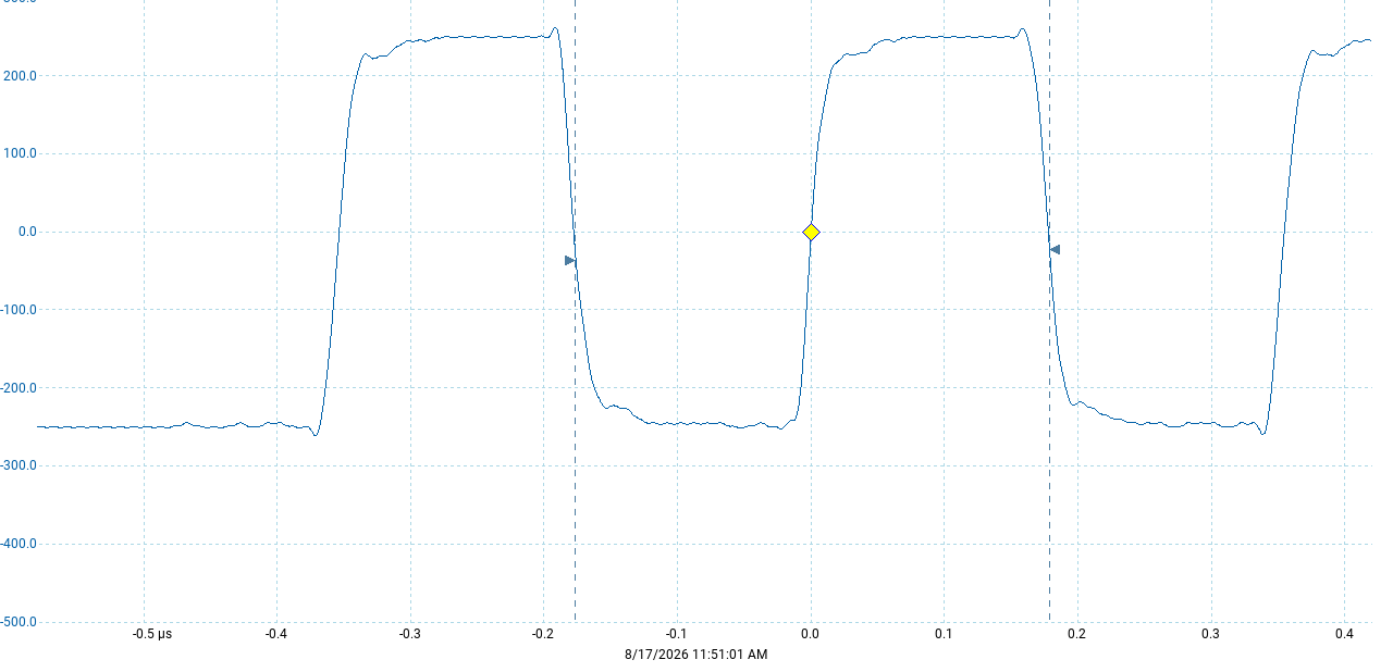
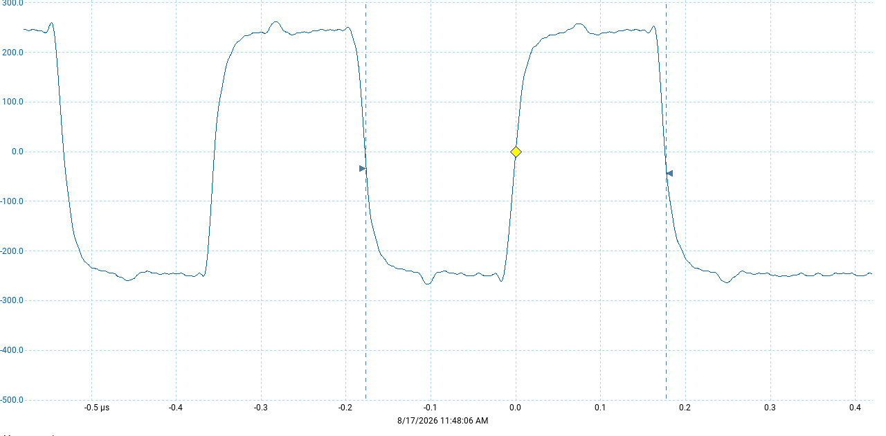
To give you some idea of the robustness of this sort of signal in coax, take a look at these images. We've used our standard digital audio cable in two different lengths to run a signal at 2.8Mbps. The top image is run through six feet of S/PDIF cable, while the bottom is run through 35 feet of the same cable. In both cases, the line is correctly terminated with a 75 ohm load and the measurements are taken at the load end. You can see a couple of things: first, the difference in attenuation is almost nil, with the voltage reaching approximately the same level in both cases. Second, you can see the accumulated impact of return loss and cable capacitance: while the waveforms are extremely similar, the "shoulder" at the end of each transition is slightly rounded. The signal is still extremely clean, and a circuit which received it accurately through six feet of cable would be unlikely to behave any differently through 35 feet. How much longer could one go? It will depend on the quality of the source signal and on the bitrate, but the reality is that very, very few people ever actually want to run S/PDIF to distances where function is likely to be a problem.
 BNCs:
BNCs:
Since this is a 75 ohm impedance connection, people ask whether they should use 75 ohm BNCs instead of RCA plugs. The answer is that (1) on most gear you'd have to do a bit of surgery to install a BNC jack, and (2) while a connector which matches the impedance of the line is always a good thing, the wavelengths are simply too long for it to matter under normal S/PDIF usage conditions. We like to use broadcast-style RCA plugs anyhow, which minimize the impedance mismatch by carrying the cable dimensions as near to the tip as possible (unlike, say, a solder-on RCA plug). Now, if you have devices with BNCs (or -- as one sees sometimes on laser-disc players -- F-connectors), that's no problem. We've got the connectors. But there's no reason to worry about running this in the typical RCA to RCA configuration.
Conclusion: Don't Worry!Fear, uncertainty and doubt are valuable commodities, and people in this market convert those into a lot of money. We all want our systems to sound their best, and when we've put money into high-quality decks, DACs and amps, we are liable to worry about the implications of attaching those devices with a modestly-priced cable, but there just isn't much difficulty in coming up with a superb S/PDIF cable. Spend the money on music instead; the artists will thank you.